
Photo-Activated Adhesive Workholding (PAAW) technology are the components and processes that enable a workpiece to be held within a manufacturing fixture using a photo-curable adhesive. The fixture maybe a shuttle fixture such as shown in Figure 1 or it may be permanently mounted in the machine tool or on a pallet. The fixture uses mechanical–optical components called grippers. Grippers serve as anchor pads on to which the adhesive is deposited and the workpiece is adhered. They also serve as the optical conduit through which curing light is transferred to the adhesive.

Figure 1. Grippers Illustrated ia a PAAW Shuttle Fixture
There are two styles of grippers: Head Out (HO) and Head In (HI) as shown in Figure 2. A Head Out gripper screws into the fixture from the workpiece side (Figure 3) and cannot be repositioned during the workpiece unload-load cycle. A Head In gripper (Figure 3) screws into the fixture from the opposite side and can be repositioned during the workpiece unload-load cycle. This functionality enables a complex workpiece to be loaded into the fixture without interfering with the gripper. It also enables twist-off workpiece de-bonding. Regardless of type, each houses a load bearing, optical conduit called a gripper pin.

Figure 2. Head Out Gripper(l), Head In Gripper(r)
Fixture-Workpiece Assemblies Incorporating Head Out Gripper

Figure 3. Fixture-Workpiece Assemblies Incorporating Head Out Gripper (l) and Head In Gripper (r)
The photo-curable, structural adhesive is deposited on top of the gripper prior to workpiece bonding as illustrated in Figure 4. The uncured adhesive, which is non-toxic, has the consistency of grease to prevent it from running off the gripper, regardless of orientation.
The workpiece is then registered relative to the fixture. This may be through the use of hard contact locators (permanently attached or removeable) as shown in Figures 5 and 6 or through the use of a transfer nest. This leaves gaps between the workpieces and the grippers which are completely filled in by the adhesive. In no case is the workpiece in direct contact with a gripper.
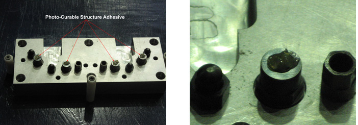
Figure 4. Photo-Curable Structural Adhesive Deposited to the Tops of Grippers

Figure 5. Locators used to Register the Workpieces
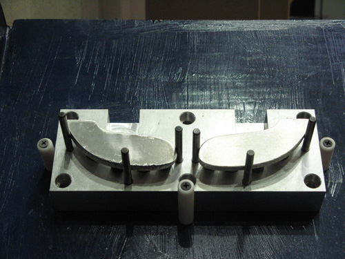
Figure 6. Workpieces Registered Relative to the Locators
Photo-curing light is sourced via a high intensity spot lamp (Figure 7). Light is transferred to the grippers via a light guide with one or more legs. The end of each leg is enclosed within a light guide shroud. Prior to the bonding process, the leg(s) of the light guide are positioned against the backsides of the grippers (Figure 8). The shroud mates with a receiving bore on the backside of the fixture to correctly align and restrain it. This allows “hands off” photo-curing of the adhesive joints.
Light is then transmitted through each gripper pin (Figure 9) into the adhesive for a duration of 20 to 60 seconds, depending on the desired quick strength of the adhesive. During this process, the adhesive polymerizes, hardens, strengthens, and adheres to both the grippers and workpiece. Shrinkage of the adhesive causes the workpieces to be gently pulled against the locator pads. The resultant adhesive joint is strong, rigid, and visco-elastic. As such it is capable of dissipating vibrational energy. It is also non-toxic.

Figure 7. Spot Lamp and 4 X 3mm Light Guide
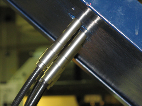
Figure 8. Light Guide Legs Positioned Against the Back Side of the Grippers

Figure 9. Photo-Cure Light Transmitted Through the Gripper Pins to Polymerize the Adhesive
Once all of the adhesive joints have been exposed to light, the light guides are withdrawn and all temporary locators are removed. The workpiece(s) is then processed as shown in Figure 10.

Figure 10. Workpieces after the Completion of the Machining Cycle
Once the last manufacturing process has been performed, the workpieces are mechanically de-bonded from the grippers. If HO grippers are used, the workpiece must be forced off of the fixture using an ejector such as shown in Figure 11. If HI grippers are used, this option exists, but the adhesive joints may also be broken by counter screwing each gripper in sequence. This is illustrated in Figure 12 for an alternative application.
Forcing is the fastest method of de-bonding, but exerts the greatest stress on the workpiece. Counter screwing the grippers exerts minimal stress on the workpiece, but takes longer to do. Which method to use depends on the strength, hardness, and stiffness of the workpiece and the number of adhesive joints holding it.

Figure 11. Spindle Mounted Ejector Used to Automatically Force the Machined Workpieces from the Head Out Grippers

Figure 12. Counter-Screwing a Head In Gripper to Twist-Off Fracture an Adhesive Joint
Depending on the de-bonding method used, a partial to full layer of hardened adhesive will be left on the grippers as shown in Figure 13. Prior to the next bonding cycle, this adhesive must be stripped off of the grippers. This can be done in many ways. The fastest and most efficient is to automatically strip it off using a spindle mounted, axial adhesive grinder as shown in Figures 14 and 15.
A peripheral grinding process is also available to strip grippers positioned orthogonally to the spindle axis. This is illustrated in Figures 16 -18 for an alternative application. These two processes coupled with a sufficient number of machine tool d.o.f. can enable complete grinding automation with no additional capital investment. Alternatively the peripheral grinding process can be carried out manually with a pneumatic grinder.

Figure 13. Residual Adhesive Left On Grippers after the Workpieces have been De-Bonded

Figure 14. Spindle Mounted , Axial Adhesive Grinder Stripping Residual Adhesive from a Gripper

Figure 15. Grippers after Adhesive Grinding Process

Figure 16. Gripper Oriented Orthogonal to Spindle Axis with Hardened Adhesive Layer

Figure 17. Spindle Mounted, Peripheral Adhesive Grinder Stripping Hardened Adhesive from a Gripper

Figure 18. Gripper after Peripheral Grinding Process
Hardened adhesive may be left on the workpiece surfaces after mechanical de-bonding. This is illustrated in Figure 19. In general this will not be an issue if these surfaces are to be machined in a subsequent set up. However if they are not, then steps must be taken to strip this adhesive off.
One popular method is to strip the adhesive off with a hot water, power spray (Figure 20). Another popular method is to soak the workpiece in a hot aqueous solution for a few minutes, and allow the adhesive to hydrolyze and lose its stick. Once removed from the bath, the hardened adhesive is easily peeled/brushed off. These and other methods are described in the E-Guide “PAAW Technology and Practice.”
 Figure 19. Hardened Adhesive left on the Workpiece Surface after Mechanical Debonding |
 Figure 20. Workpiece Surface after Hardened Adhesive was Removed by Hot Water Power |