Engineers often use a breadboard to quickly build prototypes of circuits for testing. A breadboard has a series of holes or sockets into which jumper wires are inserted to make electrical connections. The wires are easy to connect and disconnect. Some of the sockets are hard-wired to other sockets, forming a bus. Breadboards have both short buses (typically containing 5 sockets) and long buses (typically running the full length or width of the breadboard and containing many sockets, often also in groups of 5). Short buses are used for component connections, in which two to five wires may be connected to one short bus. Long buses are generally saved for high-usage connections, such as a DC voltage power supply or ground (zero volts). A bus used as ground would, for example, be called a ground bus.


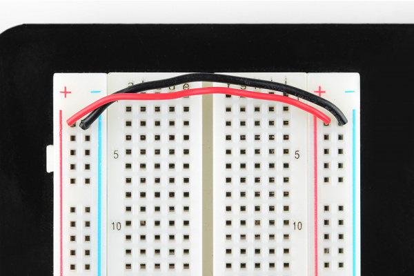
It is important to be aware that the long buses on either side are not connected, so if you want the same power source on both sides, you will need to connect the two sides with some jumper wires. Keep in mind that the markings are there just as a reference. There is no rule that says you have to plug power into the ‘+’ rail and ground into the ‘-‘rail, though it’s good practice to keep everything in order.
DIP Support
Earlier we mentioned the middle divider that isolates the two sides of a breadboard. This middle divider serves a very important purpose. Many integrated circuits, often referred to as ICs or, simply, chips, are manufactured specifically to fit onto breadboards. In order to minimize the amount of space they take up on the breadboard, they come in what is known as a Dual in-line Package, or DIP.
These DIP chips have legs that come out of both sides and fit perfectly over that middle divider. Since each leg on the IC is unique, we don’t want both sides to be connected to each other (otherwise it will BURN your CHIP!!!!). That is where the separation in the middle of the board comes in handy. Thus, we can connect components to each side of the IC without interfering with the functionality of the leg on the opposite side.
