Contents
Back to setup circuit
Waring: DO NOT CONNECT ENCODER POWER WITH MOTOR POWER! IT WILL BURN THE CIRCUIT!
DC motor
A DC motor is defined as a class of electrical motors that convert direct current electrical energy into mechanical energy. The following figure is demonstration of DC motor. A brushed DC electric motor generating torque from DC power supply by using an internal mechanical commutation. Stationary permanent magnets form the stator field. Torque is produced by the principle that any current-carrying conductor placed within an external magnetic field experiences a force, known as Lorentz force. In a motor, the magnitude of this Lorentz force (a vector represented by the green arrow), and thus the output torque, is a function for rotor angle, leading to a phenomenon known as torque ripple) Since this is a two-pole motor, the commutator consists of a split ring, so that the current reverses each half turn (180 degrees).

Encoder
As you learn in the class, encoders convert motion to an electrical signal that can be read by some type of control device in a motion control system.
Based on type of signal, encoders can be either an incremental encoder or an absolute encoder. Incremental signals do not indicate specific position, only that the position has changed. Absolute encoders, on the other hand, use a different “word” for each position, meaning that an absolute encoder provides both the indication that the position has changed and an indication of the absolute position of the encoder.
Encoders use different types of technologies to create a signal, including mechanical, optical and magnetic.
Figure 1 shows a design of incremental mechanical encoder. Each of the three connections 8A, 8B and 8C is formed of a spring arm that pushes down on the substrate. There are three signals, one connected to the metal substrate (Ground) and two others that move over the alternating substrate pattern. So, the outputs are shorted to ground as the device is rotated and then are left floating (unconnected) when the contact is in the substrate gap.

Figure 2 shows a design of incremental optical encoder. A beam of light emitted from LED passes through the Code Disk, which is patterned with opaque lines (much like the spokes on a bike wheel). As the encoder shaft rotates, the light beam from the LED is interrupted by the opaque lines on the Code Disk before being picked up by the Photodetector Assembly. This produces a pulse signal: light = on; no light = off. The signal is sent to the counter or controller, which will then send the signal to produce the desired function.

Figure 3 shows a design of incremental magnetic encoder. The magnetic encoder detects rotational position information as changes of the magnetic field, converts them into electrical signals using hall effect, and outputs them. The simplest magnetic encoder consists of a permanent magnet and a magnetic sensor. The permanent magnet is attached to the tip of a rotating body such as a motor shaft, and the magnetic sensor is fixed in a state where it is mounted on a PCB board at a position where it receives the magnetic field generated by the permanent magnet. When the permanent magnet attached to the motor shaft rotates, the direction of the magnetic field detected by the magnetic sensor changes, as a result the encoder detects the rotational position and speed of the motor shaft.

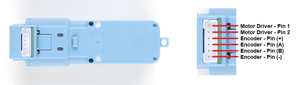
Hobby Motor with Encoder – Metal Gear (DG01D-E)
The kit includes a DG01D-E motor. It is a single hobby motor with a hall speed encoder. This motor requires a voltage between 3-9V, has a gearbox ratio of 1:48 and a speed of 90RPM at 4.5V. The embedded encoder is an incremental magnetic encoder. The voltage across encoder is determined according to the power supply voltage of the single chip microcomputer used, generally 3.3V or 5V. There are two sensors in the encoder to know the rotation and the direction.

This motor has 6 pins. Pin1 & 2 are motor terminals. Encoder pin (+) and pin (-) are used to power encoder. Encoder pin (A) and pin (B) output two sensors reading. DO NOT CONNECT SENSOR POWER TO MOTOR POWER!