Warning: Beware of the wire connection when you use TB6612FNG motor chip. Don’t use Motor supply to power signal supply. VM pin and Vcc pin should NOT be connected with each other!
However, GND pin on motor chip should be connected with GND pin on Arduino and battery ground terminal!
An H-bridge is a simple circuit that lets you control a DC motor to go backward or forward. You can use it with a microcontroller, such as an Arduino, to control motors. Here is the circuit of a H-bridge.

A DC motor spins either backward or forward, depending on how you connect the plus and the minus. If you close right top and left bottom switch, you have Vin connected to the right side of the motor and GND to the other side. And the motor will start spinning in one direction. If you instead close left top and right bottom switch, you have Vin connected to the right side and GND to the left side. And the motor spins in the opposite direction.

TB6612FNG
The kit provides a Dual TB6612FNG chip. This chip can drive two DC motor. The output current can be up to 1A. Let’s discuss the pinout for the TB6612FNG breakout. We basically have three types of pins: power, input, and output, and they are all labeled on the back of the board.
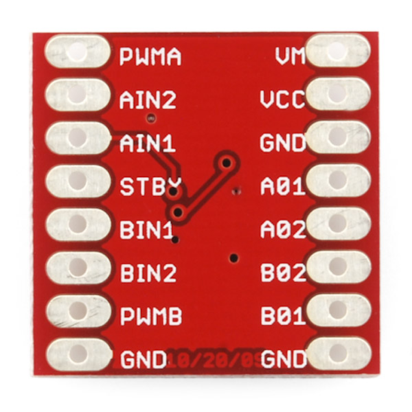
Each pin and its function are covered in the table below.
| Pin Label | Function | Power/Input/Output | Notes |
|---|---|---|---|
| VM | Motor Voltage | Power | This is where you provide power for the motors (2.2V to 13.5V). It should not be connected to VCC. |
| VCC | Logic Voltage | Power | This is the voltage to power the chip and talk to the microcontroller (2.7V to 5.5V). It should not be connected to VM. |
| GND | Ground | Power | Common Ground for both motor voltage and logic voltage (all GND pins are connected to GND pin on Arduino) |
| STBY | Standby | Input | Allows the H-bridges to work when high (has a pulldown resistor so it must actively pull high) |
| AIN1/BIN1 | Input 1 for channels A/B | Input | One of the two inputs that determines the direction. |
| AIN2/BIN2 | Input 2 for channels A/B | Input | One of the two inputs that determines the direction. |
| PWMA/PWMB | PWM input for channels A/B | Input | PWM input that controls the speed |
| A01/B01 | Output 1 for channels A/B | Output | One of the two outputs to connect the motor |
| A02/B02 | Output 2 for channels A/B | Output | One of the two outputs to connect the motor |
Now, for a quick overview of how to control each of the channels. If you are using an Arduino, don’t worry about this too much as the library takes care of all of this for you. Check how to install library on your Arduino LDE for installation. Check let’s code page for more coding help If you are using a different control platform, pay attention. When the outputs are set to High/Low your motor will run. When they are set to Low/High the motor will run in the opposite direction. In both cases, the speed is controlled by the PWM input.
| In1 | In2 | PWM | Out1 | Out2 | Mode |
|---|---|---|---|---|---|
| H | H | H/L | L | L | Short brake |
| L | H | H | L | H | CCW |
| L | H | L | L | L | Short brake |
| H | L | H | H | L | CW |
| H | L | L | L | L | Short brake |
| L | L | H | OFF | OFF | Stop |
Hardware Setup Example
Here is a Fritzing diagram to show how to connect TB6612FNG with your Arduino, motors and battery. If you want to know how to coding, Let’s coding page provides a detail coding tutorial for beginner. The example code to run following circuit is available on ETM online repository.

Here is the pin connection detail:
| Pin Label | It connects to…. | Notes |
|---|---|---|
| VM | Battery positive terminal | It should not be connected to VCC. |
| VCC | 5V pin on Arduino | It should not be connected to VM. |
| GND | Ground pin on Arduino and Battery negative terminal | Only one GND pin on TB6612FNG need to be connected to the Ground |
| STBY | Pin 9 on Arduino | Can be any digital pin on Arduino. You can define it in your code |
| AIN1 & BIN1 | Pin 2 & 7 on Arduino | Can be any digital pin on Arduino. You can define it in your code |
| AIN2 & BIN2 | Pin 4 & 8 on Arduino | Can be any digital pin on Arduino. You can define it in your code |
| PWMA/PWMB | Pin 5 & 6 | Can be any PWM pin on Arduino. You can define it in your code |
| A01/A02 | Motor A terminal pins | Direction of connection does not matter |
| B01/B02 | Motor B terminal pins | Direction of connection does not matter |