Garrett Kryt
Abstract
Handcycles offer an opportunity for wheelchair users to enjoy cycling and the outdoors. The client in this project has a customized electric-assist handcycle that is not compatible with commercially available handcycle racks. Thus, a novel handcycle rack for attachment to his vehicle was required in order to facilitate transportation of the handcycle to different cycling locations. In order to meet this requirement, a hitch mounted rear car rack was designed to be used independently by a wheelchair user. A prototype of the design was created and tested to gain feedback. This feedback was implemented, resulting in a final design that has met the client’s requirements. This rack design is extremely versatile, allowing a wheelchair user to independently mount and dismount a heavy handcycle without having to lift the full weight of the handcycle. Furthermore, when mounted on the vehicle, a user is still able to access the vehicle’s rear hatch without dismounting the handcycle. The design was successfully used by the client to transport his handcycle to several cycling destinations, and is still in use to this day.
Introduction
The client is a wheelchair user who enjoys riding his handcycle on trails and roads. While the client’s handcycle is electrically powered which allows for increased riding range, he has often found himself wanting to transport his handcycle to different riding locations that are not in practical riding distance. An attached car rack that carries the handcycle would allow the client to transport the handcycle to riding locations, allowing him more independence and enjoyment of his handcycle. The client’s handcycle weighs 80 lbs. and is an electric-assist recumbent tricycle. The handcycle is shown in Figure 1.
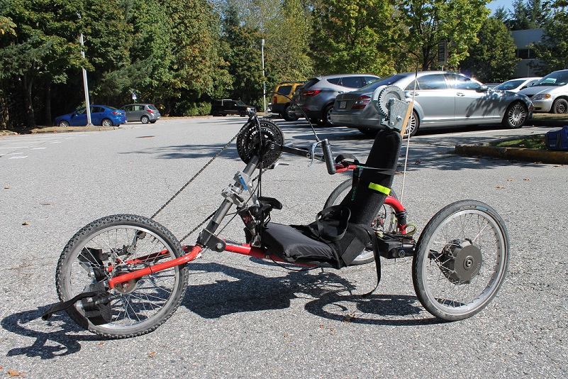
Figure 1: The Handcycle
Due to the handcycle’s custom rear suspension system, two electric motors and battery, as well as the configuration of the rear wheels and long wheelbase, no current mass-produced bicycle racks exist for the client’s handcycle. It was therefore determined that a specific rack design would be required to meet the client’s needs.
In order for the rack to be functional for the client, specific design requirements had to be met:
- The rack design had to safely support and transport the handcycle.
- The client had to be able to independently mount and dismount the handcycle from the rack.
- The rack design was required to fit onto his current vehicle (a 2012 VW Golf Wagon).
- The rack had to be designed so that the client was not required to lift the entire handcycle when mounting or dismounting the handcycle from the rack.
- The client also wanted to be able to access his trunk when the handcycle was installed.
- The rack had to stow in a compact position when not holding the handcycle, and still allow access to the trunk when stowed.
In general, it is becoming more common for electric motor assist units to be installed on handcycles. This results in handcycles that are far heavier than conventional ones, as well as often limiting the modularity of the designs (e.g. removing the wheels becomes more difficult with motors and wires). This leads to difficulty in transporting handcycles, especially by wheelchair users that have impaired physical functions such as trunk stability. While this design was undertaken for a particular client and specific handcycle, it is clear that different, more versatile, vehicle rack choices would benefit others as well, especially with independent use.
Design and Development
Three popular configurations for traditional bike racks exist. These are: roof mounted racks, trunk (or hatchback) mounted racks, and hitch mounted racks. Through market research of current bicycle and tricycle racks, it was determined that a hitch mounted rack would provide the best solution to the design requirements. A hitch mounted rack layout allows a wheelchair user to mount and dismount the handcycle in a safe and efficient manner, since hitch mounts are low to the ground compared to other alternatives. A hitch mounted rack also provides a strong platform that is able to support the weight of electric-assist handcycles safely.
To begin the design process, calculations were completed in order to determine the types of loading that the rack would need to withstand. It was realized from these calculations that the rack design should sit as close to the vehicle as possible, in order to eliminate the amount that the rack cantilevered outward from the rear of the vehicle; and also to conform to the maximum “tongue” weight able to be borne by a hitch compatible with the client’s car. It was also considered here that the bulk of the weight of the handcycle was at the rear wheels which comprise of a heavy suspension system and two large hub motors. Through sketches and discussion with the client, it was determined that an orientation where the front wheel of the handcycle sat on the hatch of the vehicle and the rear wheels rested on the rack would provide an elegant solution and minimize the amount the rack cantilevered out from the hitch.
Once an orientation had been determined, a Finite Element Analysis (FEA) as well as hand calculations were performed to determine the required design dimensions. An example of the FEA for one of the rack arms is shown in Figure 2.
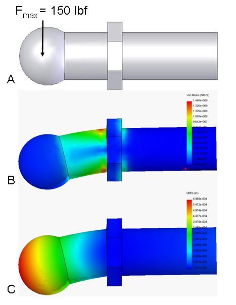
Fig. 2. Finite element stress analysis of the ball-headed bolt which connects the gas springs to the walker. (A) The maximum applied load depicted on a solid model of the bolt, made from plain carbon steel (yield strength of 2.2 x 10⁻⁸ N/m2). (B) Stress distribution under maximum load. Maximum stress was approximately 65% of yield stress. (C) Displacement of the bolt during maximum loading. Maximum displacement was 6.0 x 10⁻⁴ inches.
The rack design with the handcycle installed is shown in Figure 3. The front wheel of the handcycle is anchored using straps to the roof rack of the vehicle. The rear wheels of the handcycle rest on the wheel trays of the rack. This configuration puts the majority of the mass of the handcycle centered over the rear rack which allows it to bear the load of the handcycle safely and effectively. The configuration also allowed for easy mounting and dismounting of the handcycle using a winch system.

Figure 3: Handcycle on Rear Rack Design
The completed rack is shown in Figure 4. The rear rack fits into the hitch receiver of the vehicle. Two aluminum wheel ramps fold down to allow for the tricycle to be wheeled onto the rack. The prototype was manufactured primarily out of steel plate, with some tubular steel sections also being used for increased rigidity.
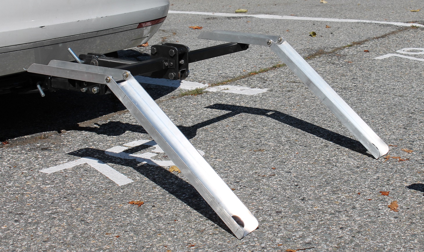
Figure 4: Completed Rear Rack Design
The rack was manufactured using a water-jet cutter, metal saw and drill press. All edges of the design were deburred and finished to provide a safe design that minimized hazards to the client and his family.
A unique feature of the design includes the modularity of the components. All the parts of the rack are put together using bolted connections. The benefit of this design aspect is that it allows easy customization of the rear rack layout based on the dimensional requirements of different handcycles and vehicles. The design is not constrained by welded joints like many rack designs. This flexibility would allow for easy adaptation of the rack to other handcycle users looking for a transport solution.
Figure 5 shows the rack in the stowed position. The wheel ramps fold away for storage when the rack is in this position. The trunk can be opened without hitting the rack, allowing the rack to stay on the back of the car even when not carrying the handcycle.

Figure 5: Rack in Stowed Position
In order to address the design requirement that the client be able to install and remove the handcycle on his own, it was determined that a winch system would allow for a safe and controllable method to mount and dismount the handcycle. Therefore, a winch was designed that easily mounts to the seat of the handcycle using wheelchair accessory clamps. A lifting strap runs from the winch up to the roof rack of the vehicle and back down to the front of the handcycle. The winch can be easily removed when the handcycle is in normal use. The winch mechanism installed on the handcycle is shown in Figure 6.

Figure 6: Winch Mechanism
The use of the winch also allowed for the ability to open and close the trunk when the handcycle is installed. Loosening the strap via the winch allows the handcycle to rotate backward about its (firmly attached) rear wheels. This in turn allows the trunk to be accessed. The handcycle in this configuration is shown in Figure 8.

Figure 7: Accessibility to Trunk
Testing and Results
The rack design was tested with the client for ease of use when dismounting and mounting the handcycle, as well as the safety and stability of the handcycle when mounted to the vehicle. The procedure for mounting and dismounting the handcycle is demonstrated in the following video:
The initial test of the prototype highlighted some clearance issues with the ability of the trunk to open and close properly. The prototype was then modified to allow proper clearance of the trunk. The winch system was also refined through testing, and with several iterations a winch and strap layout was found that allowed comfortable and independent mounting and securing of the handcycle.
After the mounting and dismounting procedures were refined, the rack was road tested to ensure safety and stability. The client has now used the rack to transport his handcycle on several trips, and he reports that the system is working perfectly.
Conclusion
To summarize, the client required a rack for his handcycle with the following design requirements:
- The rack design had to safely support and transport the handcycle.
- The client had to be able to independently mount and dismount the handcycle from the rack.
- The rack design was required to fit onto his current vehicle.
- The rack had to be designed so that the client was not required to lift the handcycle when mounting or dismounting the handcycle from the rack.
- The client also wanted to be able to access his trunk when the handcycle was installed.
- The rack had to stow in a compact position when not holding the handcycle, and still allow access to the trunk when stowed.
Through development and analysis, a rack design was developed that safely supports the handcycle, works with a hitch on the client’s vehicle, and provides access to the trunk when the handcycle is on or off the vehicle. The rack can be easily stowed when not in use into an unobtrusive position while still allowing trunk access.
Of particular interest in the design process included the development of the winch system and ultimately the layout of having the front wheel resting on the hatch of the vehicle. This orientation of the handcycle came through specific discussion with the client when testing the rack. The ability for the client to use the winch to mount and dismount the handcycle allows him to safely control the process and does not require him to lift the full weight of the handcycle. Recognizing the need for a winch system highlights the type of design consideration that does not come from computer simulation but instead from product testing and client feedback.
The ability to access the trunk when the handcycle is on the rack has been of real benefit to the client. Groceries and gear can be put into the trunk even when the handcycle is mounted and the client’s wheelchair can be stowed by his wife in the trunk when the whole family travels together. This design feature that allows trunk access really highlights the versatility of this rack design.
The resulting rack design has met all design requirements and provided the client a safe and versatile way to transport his handcycle.

Figure 8: The Client with the Completed Design
Acknowledgements
I would like to thank Dr. Jaimie Borisoff for the opportunity to work with him on this project, as well as for the opportunity to work at BCIT’s Rehabilitation Engineering Design Lab. I would also like to thank Dan Leland for his help in manufacturing the prototype.