Author Archives: Ran Chen

Convergence exploration for k points and cutoff energy based on the model of a hydrogen atom on Cu(111) surface HCP site

Introduction

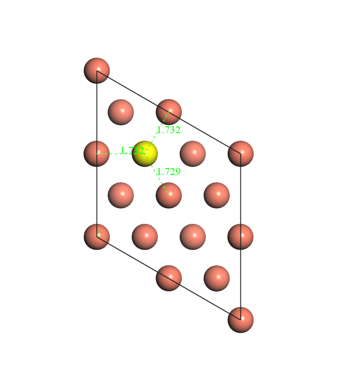
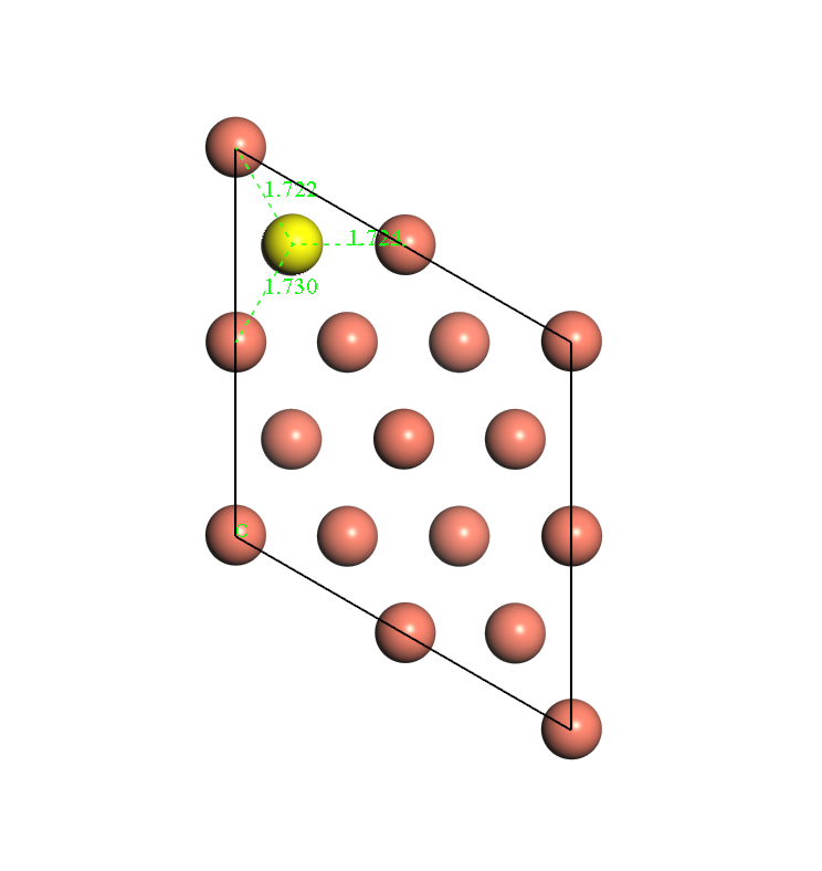
This post is aimed at exploring the convergence of k points and cutoff energy. The model chosen here is one hydrogen atom on copper(111) surface HCP site.  The model of copper surface in one periodic volume is 1*1 unit cell in x-y plane and 4 layers in z direction. Vacuum is in z direction and its thickness is 10 Å.

Fig. 1 A top view of the model

Fig. 2 A side view of the model


CASTEP tool package is adopted for all calculations in this post [1].

For the purpose of simplifying the model and reducing computational cost, during geometry optimization,  all copper atoms and x, y coordinates of H are fixed and H is just allowed to move in z direction.

The initial calculation setting for geometry optimization is:

Functional: GGA PBE [2]

Pseudopotentials: OTFG ultrasoft

Relativistic treatment: Koelling-Hamon

SCF tolerance: 5*10^-7 eV/atom

Max SCF cycles: 100

Dipole correction: not applied

Cutoff energy: 600 eV

K points: 11*11*2

After geometry optimization, a series of finite difference calculations are conducted by only changing cutoff energy and k points. The movement step  adopted here is 0.05Å in z direction, up and down respective to equilibrium position. The energy difference of three positions is adopted as convergence indicator, named as ΔE.

Since the only freedom here is H movement in z direction, we define the indicator ΔE to be:

\begin{equation} \Delta E =  E(+ \delta z) + E (- \delta z) – 2 E_0 \end{equation}

E0 is the energy for the system at equilibrium. E(+δz) means the energy of the system after H moving away from the copper surface in z direction with one step (0.05Å). E(-δz) has the opposite meaning.

The indicator is the numerator of mass-weighted Hessian Matrix and since the denominator is constant for this model the indicator shows the convergence of vibration frequency of H actually.

Results

Cutoff energy

K mesh is fixed at 11*11*2, and just cutoff energy is changed.

Calculation results are shown in Table 1. and Fig. 1. All energies are in the unite of eV.

E_cut 1/E_cut E0 E(+δz) E(-δz) ΔE
300 0.003333333 -6734.207987 -6734.201406 -6734.203442 0.011127427
350 0.002857143 -6737.770064 -6737.765333 -6737.763871 0.010923297
400 0.0025 -6738.585562 -6738.581103 -6738.578878 0.011143039
450 0.002222222 -6738.741297 -6738.736179 -6738.735176 0.011238688
500 0.002 -6738.76858 -6738.763114 -6738.7628 0.011244911
550 0.001818182 -6738.777772 -6738.772113 -6738.772165 0.011265619
600 0.001666667 -6738.78372 -6738.777944 -6738.778252 0.011242922
700 0.001428571 -6738.789645 -6738.783725 -6738.784317 0.011249237

Table 1

Fig. 3 the plot of ΔE vs reciprocal of cutoff energy

So A numerical guess rather than a strictly theoretical conclusion based on these data points is when we have an infinitely large cutoff energy for a fixed geometry with some specific setting, we should converge to a certain number for our indicator ΔE. When the cutoff energy goes smaller, we will have more numerical noise and the numbers will potentially deviate away from the ‘true value’ which is given by the infinitely large cutoff energy. The guess is visualized in Fig. 2.

Fig. 4 a schematic plot showing the extreme situation of cutoff energy’s effect on ΔE

A part of Fig. 2 that is zoomed up to show details is shown in Fig. 3.

Fig.5 a detailed part of Fig. 2

As we can see from Fig. 3, a smaller cutoff energy will potentially give a larger deviation from the ‘true value’. Or smaller cutoff energies will give a larger range of deviation from the ‘true value’.

The exact pattern may be dependent on the indicator of convergence we choose. The practical implementation of cutoff energy in CASTEP codes will affect the pattern as well. But the tendency could be general for cutoff energy’s convergence path.

And for this specific model, the difference of ΔE from 600eV to 700eV is around 0.000006 eV. If our tolerance for ΔE is at the magnitude of 0.00001 eV, choosing 600eV as our cutoff energy under the condition of using 11*11*2 for k points is acceptable. And the converged ΔE could be 0.01124 eV.

K points

Cutoff energy is fixed at 600 eV, and just k points is changed.

First, a test for k points in z direction is conducted. The results are shown in Table 2. All energies are in the unit of eV. The difference of energies calculated from k*k*2 and k*k*1 is at the magnitude of 10^-5 eV. k means the number of k points in x or y direction. If we raise our tolerance for energy difference up to 0.0001, it could be acceptable to use ‘1’ for z direction and just change the number of k points in x and y direction for following calculations in order to reduce the computational cost.

k mesh E0 k mesh E0 energy difference between k*k*2 and k*k*1
7x7x1 -6738.709562 7x7x2 -6738.709586 -2.4000E-05
8x8x1 -6738.731698 8x8x2 -6738.73171 -1.2075E-05
9x9x1 -6738.75047 9x9x2 -6738.750535 -6.4864E-05
10x10x1 -6738.769096 10x10x2 -6738.769144 -4.8546E-05
11x11x1 -6738.783685 11x11x2 -6738.78372 -3.5046E-05
12x12x1 -6738.775101 12x12x2 -6738.775133 -3.2509E-05
13x13x1 -6738.800963 13x13x2 -6738.800992 -2.8743E-05
14x14x1 -6738.774423 14x14x2 -6738.774454 -3.1116E-05
15x15x1 -6738.795033 15x15x2 -6738.795057 -2.4665E-05

Table 2a

In order to make the convergence test for k points in z direction more convincing, we calculate 7*7*3 as well.

k mesh 7*7*1 7*7*2 7*7*3
E0 -6738.709562 -6738.709586 -6738.709615
Energy difference from 7*7*1 0 2.4E-05 5.3E-05

Table 2b

As we can see, the energy difference between 7*7*3 and 7*7*1 is still at 10^-5 magnitude.

Results for a series of k*k*1 calculations are shown in Table 3 and Fig. 4. Energies are in the unit of eV.

k-mesh k 1/k E0 E(+δz) E(-δz) ΔE
3*3*1 3 0.333333333 -6739.47838 -6739.489468 -6739.45571 0.011580839
5*5*1 5 0.2 -6738.742468 -6738.746554 -6738.727462 0.010920861
7x7x1 7 0.142857143 -6738.709562 -6738.706263 -6738.702423 0.010438667
9x9x1 9 0.111111111 -6738.75047 -6738.743514 -6738.746635 0.010791582
11x11x1 11 0.090909091 -6738.783685 -6738.777909 -6738.778218 0.01124229
13x13x1 13 0.076923077 -6738.800963 -6738.796022 -6738.79491 0.010994729
15x15x1 15 0.066666667 -6738.795033 -6738.791071 -6738.788042 0.010951909
16x16x1 16 0.0625 -6738.770667 -6738.766317 -6738.763964 0.011054494

Table 3

Fig. 6 the plot of ΔE vs 1/k

Based on data points in Fig. 4, we can see the convergence of k points has a similar pattern with cutoff energy. Difference of ΔE from 15*15*1 to 16*16*1 is still at the magnitude of 10^-3 eV, which is not desirable. We can do the fitting to get the converged number of ΔE, the ‘true value’, given by infinitely large k points. The candidate fitting function could be a*exp(bx)*sin(c*x) and a,b,c are parameters needing to be fitted. Since the number of data points here is small the fitting would be loose. Instead of calculating more data points, another cheap way of approximating the ‘true value’ is doing average for last five ΔE numbers (9*9*1, 11*11*1, 13*13*1, 15*15*1, 16*16*1). The average is 0.0110070008 eV and if we truncate it to 10^-4 eV, we have 0.0110 eV, which is different from above-mentioned number, ‘0.01124 eV’, calculated from the setting of 11*11*2 as k points and 600 eV as cutoff energy. The inconsistency of using k*k*2 and k*k*1 in different tests could result in some difference. But as mentioned before, the difference should be minor. The main reason might be the average is adopted here. The number of converged ΔE could be 0.011 eV with the cost of losing some precision.

Conclusion

Based on the ΔE = 0.011 eV, vibration frequency of H on Cu(111) surface HCP site in z direction is 3.266*10^13 Hz.

Regardless of particularity of codes and models, we can say that the energy difference ΔE defined above calculated from DFT methods by using a specific k points and cutoff energy can only be trusted in a range around that number given by the infinitely large k points and cutoff energy. The larger the k points and cutoff energy is, the narrower the range is.

Acknowledge

The optimized geometry for all calculations in this post is provided by Mark Hagemann. Mark Hagemann and Brett Green also did calculations for E0 in Table 1; calculations in Table 2; calculations for E0 in Table 3 from 7*7*1 to 16*16*1.

The energy numbers for 7*7*1, 7*7*2 shared by Mark were ‘final energy(E)’ but other energy numbers are ‘final free energy(E-TS)’. So I changed Mark’s data for E0 at 7*7*1, -6738.689838(E), to -6738.709562(E-TS) for consistency.

Thank Mark and Brett for sharing their data.

Reference

  1. First principles methods using CASTEP” Zeitschrift fuer Kristallographie 220(5-6) pp. 567-570 (2005) S. J. Clark, M. D. Segall, C. J. Pickard, P. J. Hasnip, M. J. Probert, K. Refson, M. C. Payne
  2. J. P. Perdew, K. Burke, and M. Ernzerhof Phys. Rev. Lett. 77, 3865 (1996)


How initial estimates change convergence properties of bisection method and Newton’s method

Method Introduction

There are various methods that could search local minimums for a function. This locally lowest value search could be called numerical optimization, which could happen in one dimension or  more than one dimension. Normally, the later one is more difficult.

Here, only optimization in one dimension is studied and methods adopted are bisection method and Newton’s method.

These two methods are iterative and can only provide approximations, which is controlled by the convergence criterion. An initial estimate is needed to use these two methods and no guidance is provided by the methods themselves. So the following content will study how the initial guess changes convergence properties of these two methods.

The function used here is f(x)=exp(-x)cos(x). Ranges selected for bisection method are (1.2, 2.4), (1.4, 2.6), (1.6, 2.8), (1.8, 3.0), (2.0, 3.2), (2.2, 3.4). Initial estimates are boundary values of each range for bisection method. Initial estimates selected for Newton’s method are 1.2, 1.4, 1.6, 1.8, 2.0, 2.2, 2.4, 2.6, 2.8, 3.0, 3.2, 3.4. The initial estimates of Newton’s method are consistent with that of bisection method, which is designed for comparison between these two methods.

A reference local minimum for the studied function is x=2.356194490… . How many decimal places is determined by the precision we set. The convergence criterion used here is 0.000001(1E-06). The range selection for bisection is stopped at (2.2, 3.4) (the change step is 0.2 between each range) otherwise the reference value will fall outside the range.

Another tricky thing is that bisection method has two initial estimates, which form a range for later iteration, while Newton’s method only needs one. So, when we doing comparison, choosing which value for Newton’s method should be paid attention. Since Newton’s method converges to different local minimums with bisection method at 3.0, 3.2, 3.4, smaller boundary values of each range(1.2, 1.4, 1.6, 1.8, 2.0, 2.2) are adopted for Newton’s method when we comparing these two methods at each range.

Calculation Results

The difference of each step ε is defined as x value is this iteration minus x value in last iteration.

Following figures show the calculation results. Full data could be got through the link attach at the end of this post.

Comparison for convergence property between bisection and newton’s method

Range (1.2, 2.4)

Range (1.2, 2.4) is chosen for bisection method, the local minimum is 2.356194.

For New’s method, 1.2 is the initial estimate. The local minimum is  2.356194.

Fig 1 shows the convergence properties of bisection method and Newton’s method. Fig 2 shows a part of Fig1 in order to show the convergence detail.

 Fig1. difference of each step ε vs iteration steps at range (1.2, 2.4)


Fig2. part of Fig1 in order to show details of convergence

Both of the methods converge to the same local minimum under the convergence criterion of 1E-06. But the Newton’s method converges needing less steps. The same pattern could be found for following ranges.

Range (1.4, 2.6)

Range (1.4, 2.6) is chosen for bisection method. The local minimum is 2.356194.

For Newton’s method, the initial estimate is 1.4. The local minimum is 2.356194.

Fig 3 and 4 show the convergence properties of the two methods.

Fig 3. difference of each step ε vs iteration steps at range (1.4, 2.6)


Fig 4. part of Fig3 in order to show details of convergence

Range (1.6, 2.8)

Range (1.6, 2.8) is chosen for bisection method. The local minimum is 2.356194.

For Newton’s method, the initial estimate is 1.6. The local minimum is 2.356194.

Fig 5 and 6 show the convergence properties of the two methods.

Fig 5. difference of each step ε vs iteration steps at range (1.6, 2.8)


Fig 6. part of Fig5 in order to show details of convergence

Range (1.8, 3.0)

Range (1.8, 3.0) is chosen for bisection method. The local minimum is 2.356194.

For Newton’s method, the initial estimate is 1.8. The local minimum is 2.356194.

Fig 7 and 8 show the convergence properties of the two methods.

Fig 7. difference of each step ε vs iteration steps at range (1.8, 3.0)

Fig 8. part of Fig 7 in order to show details of convergence

Range (2.0, 3.2)

Range (2.0, 3.2) is chosen for bisection method. The local minimum is 2.356194.

For Newton’s method, the initial estimate is 2.0. The local minimum is 2.356194.

Fig 9 and 10 show the convergence properties of the two methods.

Fig 9. difference of each step ε vs iteration steps at range (2.0, 3.2)

Fig 10. part of Fig 9 in order to show details of convergence

Range (2.2, 3.4)

Range (2.2, 3.4) is chosen for bisection method. The local minimum is 2.356194.

For Newton’s method, the initial estimate is 2.2. The local minimum is 2.356194.

Fig 11 and 12 show the convergence properties of the two methods.

Fig 11. difference of each step ε vs iteration steps at range (2.2, 3.4)


Fig 12. part of Fig 11 in order to show details of convergence


Study for convergence property for bisection and Newton’s method, respectively

The Bisection method

Fig 13 shows the convergence property of bisection method at different range. When only one local minimum exits in the ranges, we can say that optimization in different ranges has the same convergence path, which could be confirmed from data in attachment.

Fig 13. difference of each step ε vs iteration steps for bisection method at different ranges

Newton’s method

Besides 1.2, 1.4, 1.6, 1.8, 2.0, 2.2, Newton’s method could get the same local minimum 2.356194 at 2.4, 2.6, 2.8 for the initial estimate.So the new initial guesses are included for the comparison, which is shown in Fig 14. Only around the local minimum, we can say that the convergence is faster if the initial estimate is closer to the local minimum. When the initial estimate is far from the local minimum, the argument is not right. For example, the convergence is faster when the initial estimate is 1.2 compared with the situation when the initial estimate is 2.8, while 2.8 is closer to 2.356194. The explanation could be that the Newton’s method uses the tangent of the first-order derivative function of the original function to find points where  the first-order derivative is zero. This search is determined by the initial estimate and the curve’s shape of the derivative function.

Fig 14. difference of each step ε vs iteration steps for Newton’s method at different initial estimates


Another local minimum found by Newton’s method

When the initial estimate is 3.0, 3.2, 3.4, Newton’s method converges to different numbers from 2.356194. Results are shown in Table 13. The convergence value could be a local minimum when the second-order derivative is positive. So when the initial estimate is 3.0, 3.2, 3.4, the convergence values are local maximum actually. Then some negative initial estimates are tried. The new local minimum could be -3.926990.

the initial estimate convergence value second-order derivative
other 2.356194 0.134
3.0 -63.617251 -0.613
3.2 11.780972 -1.081
3.4 5.497787 -0.005
-3.0 2.356194 0.134
-4.0 -3.926990 71.776

Table 1 some trials to find other local minimums


Conclusion

Comparing how fast (‘fast’ in this post means needing less iteration steps)  the convergence happens for the two methods makes more sense if they converge to the same value. So the initial estimate is chosen to let bisection and Newton’s method converge to the same value. Under this condition, Newton’s method converges faster, in other words, needs less iteration steps than bisection method. A little change for the initial estimate that does not change the convergence value will still give the same fact that Newton’s method converges with less iteration steps.

Bisection method studied respectively, if the ranges chosen for initial estimates has only one minimum, changing the initial estimate will not change the convergence path, which could be seen in Fig 13.

For Newton’s method, if the initial estimate is close to the local minimum, the convergence could need less iteration steps, which however does not mean relatively far initial estimates will guarantee a convergence with more steps. The convergence property is related to the function’s property as well. For the function studied in this post exp(-x)cos(x), we can have other variations like exp(-ax)cos(x) or exp(-x)cos(ax), in which a is a positive number. As we can see, the function has two parts, ‘exp’ and ‘cos’. the first part determines the functions value especially when x takes values far away from 0 and the second part determines the oscillation period. If we introduce parameter ‘a’ into this function, we can expect we will have different function curves and different local minimums.

Here are some plots showing the curves of f(x) = exp(-x)cos(x) and its two variations in different ranges.

Fig 15. f(x) in range(1, 3), we can see the local minimum at 2.356194.

Fig 16. f(x) in range (-5, 5), we can see the local minimum at -3.926990.

Fig 17. f(x) in range (-100, 100), we can see another local minimum near -100.

Fig 18. f(x) and its variations: exp(-2x)cos(x) and exp(-x)cos(2x) in range (-5, 5)

Fig 19. f(x) and its variations: exp(-2x)cos(x) and exp(-x)cos(2x) in range (-100, 100)

From these plots, we can verify above-mentioned local minimums for f(x) and see f(x) and its variations have different curve shapes, which would affect convergence of Newton’s method.

Another point of view is if the initial estimate is far enough, a new extremum might be found. But whether it is a local minimum is determined by the sigh of its second-order derivative.

Reference

W. H. Press, S. A. Teukolsky, W. T. Vetterling, and B. P. Flannery, Numerical Recipes in C++: The Art of Scientific Computing, Cambridge University Press, Cambridge, UK, 2002.

Support information

Calculation data could be got through this link:

https://psu.box.com/s/h1ha1f482o6qbj0j3idk4b5nrmbxkhld


Energy and frequency calculation for hydrogen on Cu(111)

Introduction

Hydrogen atoms on Cu(111) can bind in two distinct threefold sites, HCP and FCC. This post is aimed at showing energy difference between these two sites without and with zero point energy correction by using DFT calculation.

For harmonic oscillator, in classical mechanics, the energy for equilibrium state is zero kinetic energy plus potential energy E0; But in quantum mechanics, due to Heisenburg uncertainty principle, the energy changes to: \begin{equation} E = E_0 + \Sigma_i \frac{h \nu_i}{2} \end{equation}

E0 is still the potential energy and ν is the vibrational frequency of the oscillator. Zero point energy is defined as: \begin{equation} E_{ZPE} = \Sigma_i \frac{ h \nu_i}{2} \end{equation}

Normally, zero point energy is not trivial for light atoms, like H.
In order to get zero point energy, vibration frequencies of H on Cu surface are needed and these frequencies are calculated from mass-weighed Hessian Matrix A, which has a relation with Hessian matrix H:
\begin{equation} A_{ij} = H_{ij} / m_i \end{equation}
where mi is mass of the atom associated with ith coordinate. In this post m =1.00794*1.66054*10^-27 kg. The eigenvalues of matrix A λ could give vibration frequencies by: \begin{equation} \nu_i = \sqrt{\lambda}/2\pi \end{equation}

Constructing Hessian Matrix requires us to do second-order differentiation for energy to coordinate: \begin{equation} H_{ij} = (\frac{\partial E}{\partial x_i \partial x_j})_{x=0} \end{equation}

which could be obtained from finite difference approximation. The method used in this post is the simple one which involving three points in one differentiation:

\begin{equation} H_{ij} \simeq \frac{E(\delta x_i, \delta x_j) – 2 E_0 + E(- \delta x_i, – \delta x_j)}{\delta x_i \delta x_j} \end{equation}

The model built in this post is H on the Cu(111) surface with three layers, vacuum above the surface is 10 Å. 2*2 supercell is adopted in case the hydrogen atoms in periodic structure are too close.

Before individual energy calculations, geometry optimization is conducted first. The hydrogen atom is put near the HCP site (or FCC site). Bottom two layers are fixed and the first layer and hydrogen are allowed to relax. After geometry optimization is finished, the distance between H atom and nearest three Cu atom could be checked. Fig. 1, 2 and 3 show the diagrams of the model. Fig. 1 shows that after geometry optimization, the distances between H atom and nearest three Cu atoms are close. So does Fig. 2. Fig.3 shows the side-view of the model.


Fig. 1 diagram for HCP site after geometry optimization

Fig. 2 diagram for FCC site after geometry optimization


Fig. 3 side-view of ‘H on Cu(111)’ model


Based on the geometry optimized, H atom is moved to three directions (x, y, z) according to elements in Hessian Matrix and energy calculation is conducted after each movement. The move step is 0.04Å.

Functional: GGA PBE[1]; k points: 5*5*1 ; cutoff energy: 408.2 eV; SCF tolerence: 2.0*10^-6 eV/atom; Pseudopotentials: OTFG ultrasoft, for Cu: inner shell is 1s2 2s2 2p6 3s2 3p6, outer shell is 3d10 4s1, for H: outer shell is 1s1; dipole correction is included since the model is not symmetric.

(‘CASTEP’ calculation module[2] is adopted for all calculations)

Calculation results

HCP site

Table 1 shows the calculation results at HCP site. δx means movement of H atom in x direction. δy and δz have similar meaning. δx=δy=δz=0 means the result of geometry optimization. ‘1’ means one movement which is 0.04Å.

Table 1.

δx δy δz Energy (eV)
0 0 0  -2.01835196E+004
1 0 0  -2.01834837E+004
1 1 0  -2.01834811E+004
1 0 1  -2.01835046E+004
0 1 0  -2.01834837E+004
1 1 0  -2.01834811E+004
0 1 1  -2.01835050E+004
0 0 1  -2.01835070E+004
1 0 1  -2.01835046E+004
0 1 1  -2.01835050E+004
-1 0 0  -2.01834834E+004
-1 -1 0  -2.01834815E+004
-1 0 -1  -2.01834479E+004
0 -1 0  -2.01834837E+004
-1 -1 0  -2.01834815E+004
0 -1 -1  -2.01834479E+004
0 0 -1  -2.01834499E+004
-1 0 -1  -2.01834479E+004
0 -1 -1  -2.01834479E+004

Mass-weighted Hessian matrix calculated based on data in Table 1:

[  4.31362677e+29          2.29142726e+29             2.59356062e+29]

[  2.29142726e+29          4.29567826e+29             2.58159494e+29]

[  2.59356062e+29          2.58159494e+29             4.92387633e+29]

Eigenvalues of the matrix are 9.51368753 e+29, 2.01335272 e+29, 2.00614111 e+29.

Vibration frequencies of H atom at HCP site (s^-1) are 1.5524*10^14, 0.7141*10^14, 0.7129*10^14.

Zero point energy for H at HCP site is 0.6161 eV.


FCC site

Table 2 shows the calculation results at FCC site.

Table 2.

δx δy δz Energy (eV)
0 0 0  -2.01835358E+004
1 0 0  -2.01834780E+004
1 1 0  -2.01834759E+004
1 0 1  -2.01835094E+004
0 1 0  -2.01834777E+004
1 1 0  -2.01834759E+004
0 1 1  -2.01835091E+004
0 0 1  -2.01835112E+004
1 0 1  -2.01835094E+004
0 1 1  -2.01835091E+004
-1 0 0  -2.01834783E+004
-1 -1 0  -2.01834765E+004
-1 0 -1  -2.01834259E+004
0 -1 0  -2.01834784E+004
-1 -1 0  -2.01834765E+004
0 -1 -1  -2.01834261E+004
0 0 -1  -2.01834280E+004
-1 0 -1  -2.01834259E+004
0 -1 -1  -2.01834261E+004

Mass-weighted Hessian matrix calculated based on data in Table 2:

[  6.89821314e+29          3.56577192e+29             4.07730464e+29]

[  3.56577192e+29          6.91017881e+29             4.08029606e+29]

[  4.07730464e+29          4.08029606e+29             7.92127857e+29]

Eigenvalues of the matrix are 1.51030097 e+30, 3.33850851 e+29, 3.28815230 e+29.

Vibration frequencies of H atom at FCC site (s^-1) are 1.9559*10^14, 0.9196*10^14, 0.9126*10^14

Zero point energy for H at FCC site is 0.7833 eV.

Conclusion:

Table 3 shows the energies of H at two three-hold sites on Cu(111) without and with zero point energy.

Table 3

Energy (eV) HCP FCC E(HCP) – E(FCC)
Without ZPE -20183.5196 -20183.5358 0.0162
With ZPE -20182.9034 -20182.7525 -0.1509

When zero point energy is not included, the H atom on FCC site has lower energy. But when zero point energy is included, the H atom on HCP site has lower energy. Zero point energy is important for light atoms, like H and should be considered for systems involving light atoms.

Reference:

  1. J. P. Perdew, K. Burke, and M. Ernzerhof Phys. Rev. Lett. 77, 3865 (1996)
  2. First principles methods using CASTEP” Zeitschrift fuer Kristallographie 220(5-6) pp. 567-570 (2005) S. J. Clark, M. D. Segall, C. J. Pickard, P. J. Hasnip, M. J. Probert, K. Refson, M. C. Payne
  3. R. Ryberg, Carbon-Monoxide Adsorbed on Cu(100) Studied by Infrared-Spectroscopy, Surf. Sci. 114 (1982), 627 641.

Searching for the Lattice Parameter of ScAl

Lattice Structure description: 

ScAl has the same type of structure that CsCl, which is simple cubic cell. The cell vector could be (1, 0, 0), (0, 1, 0), (0, 0, 1). Fractional coordinates for Cs could be (0, 0, 0) and for Al could be (0.5, 0.5, 0.5). Diagram for this structure is shown in Fig 1.

Fig1 Golden spheres are Sc, the brown shere is Al.

Since ScAl has simple cubic structure, We just need to adjust lattice parameter a in order to predict its structure. Idea is calculate total free energy for different parameters and find out the energetically favorable one.

DFT calculation is adopted for this search.

Cutoff energy test: 

A test is done to find a proper cutoff energy. Fixing other setting: functional: GGA PBE, k points: 6*6*6, lattice parameter a=4.0Å, we change cutoff energy and compare their total free energy results. Results are shown in Table 1. Energy difference between cutoff energy ‘460 eV’ and ‘560 eV’ is less than 0.02eV. If time cost in considered and total free energy resolution is controlled at 0.02 eV, using ‘460 eV’ for cutoff energy for following calculations is an acceptable choice.

cutoff energy(eV) total free energy(eV)
60 -1140.936931
160 -1347.963162
260 -1379.612688
360 -1383.327654
460 -1383.662277
560 -1383.681389
660 -1383.681690

Table 1

K point test:

functional: GGA PBE, cutoff energy: 460eV are fixed and lattice parameter a is changed.

K points in default will change with lattice parameter. (CASTEP tool is used here, ‘default’ meaning default number for k points in CASTEP tool)

Results are shown in Table 2 .

lattice parameter a(Å) k points total free energy (eV)
2.0000 14*14*14 -1336.132886
2.6000 10*10*10 -1376.299647
2.7000 10*10*10 -1379.066514
2.8000 10*10*10 -1381.168776
2.9000 10*10*10 -1382.723256
3.0000 8*8*8 -1383.831689
3.1000 8*8*8 -1384.578369
3.2000 8*8*8 -1385.031976
3.3000 8*8*8 -1385.254431
3.3600 8*8*8 -1385.298682
3.3700 8*8*8 -1385.300556
3.3750 8*8*8 -1385.300611
3.3800 8*8*8 -1385.300591
3.3850 8*8*8 -1385.299964
3.3900 8*8*8 -1385.29928
3.4000 8*8*8 -1385.296417
3.4200 8*8*8 -1385.287388
4.0000 6*6*6 -1383.662277
5.0000 6*6*6 -1379.859133
6.0000 4*4*4 -1377.783054

Table 2

If density of k points is defined as number of k points in one direction over k space parameter in that direction, this according change of k point might have a purpose of keeping density of k point unchanged. Since the lengths of lattice vector in cell and lattice vector in k space have inverse proportion relation. So in this simple cubic system, expectation would be that number of k points in one direction times lattice parameter ‘a’ should lead to a constant. Obviously, this expectation is not obeyed in this test.

K points will effect the precision and time cost of a calculation, so finding a balance point of precision and efficiency means  we need to find a suitable k points. This ‘finding a balance’ situation occurs as well when we deal with cutoff energy.

So which k point choice is suitable for this calculation? We can discuss this based on calculation results.

Fig 2 and Fig 3 show the search for lattice parameter. Relatively, one is rough, the other is fine.

Fig 2

Fig 3

We can see the parameter range which is located at energy valley is (3.36, 3.40). At this range, the k point is set as ‘8*8*8’ and in this range the finest search step is 0.005Å.

In ‘cutoff energy test’, ‘460 eV’ is used for cutoff energy so that resolution for total free energy is set to ‘0.02 eV’. Please notice that the ‘0.02 eV’ resolution actually also includes the setting of k points as ‘6*6*6’. And in the range we care about most adopts ‘8*8*8’ k point setting which should give precise enough results for this search. Energy numbers in table 2 for range (3.36, 3.40) do have difference less than 0.02 eV, which actually is less than 0.002 eV. So we can say that if ‘460 eV’ is adopted for cutoff energy, ‘8*8*8’ k point setting is ‘safe enough’ for this calculation. Of course, accordingly, it will be dangerous to make a prediction for lattice parameter beyond the precision of ‘0.005Å’.

Convergence test, however, is still done for k points, at a=4.0Å , cutoff energy=460 eV. Results are shown in Table 3.

k points total free energy(eV)
4*4*4 -1383.589307
5*5*5 -1383.619788
6*6*6 -1383.662277
7*7*7 -1383.635492
8*8*8 -1383.633134
9*9*9 -1383.639153
10*10*10 -1383.636616
11*11*11 -1383.63629
12*12*12 -1383.637744

Table 3

From data in this table, total free energy’s difference between ‘8*8*8’ and ‘9*9*9’ is less than 0.02 eV, which supports the point that ‘8*8*8’ setting for k points is precise enough under resolution of 0.02 eV for total free energy.  Consistent with expectation, with increasing number of k points, we have smaller energy difference.

‘8*8*8′ for k points is adopted for lattice parameters outside (3.36, 3.40) in order to constrain variables when comparing different parameters’ energy. And for parameters in (2.00, 2.90), calculations have larger k points so it would be meaningless to re-calculate these points. Just using ‘8*8*8’ k points re-calculate points with a=4.00, 5.00, 6.00 Å. Results and comparison are shown in Table 4.

lattice parameter(Å) total free energy with 8*8*8 k points(eV) total free energy with default k points(eV)
4.000 -1383.633134  -1383.662277
5.000 -1379.864649 -1383.662277
6.000 -1377.763773  -1377.783054

Table 4

From data in the table, we can see that with ‘8*8*8’ k points, total free energy for these points goes higher, which does not affect our search for lowest energy point.

Conclusion:

If ‘460 eV’ cutoff energy and ‘0.02 eV’ precision for total free energy is adopted, ‘8*8*8’ k points setting could provide precise enough for the search of lattice parameter. At the same time the precision of this parameter search is limited at ‘0.005Å’.

Based on the calculation results and just considering minimizing total free energy, ScAl should have a lattice parameter around 3.375Å.

If more decimal place is wanted for this prediction, larger cutoff energy and k points should be adopted.

Reference:

First principles methods using CASTEP. Zeitschrift fuer Kristallographie 220(5-6) pp. 567-570 (2005) S. J. Clark, M. D. Segall, C. J. Pickard, P. J. Hasnip, M. J. Probert, K. Refson, M. C. Payne