REVERSE ELECTRODIALYSIS (RED)

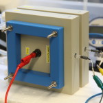
Figure 1.(B) RED stack sold by the company PCCell (Germany), with one electrode lead showing (red) and two reference electrodes (attached to yellow and green wires).(Photo credit: Xiuping Zhu & Xiaoyuan Zhang)
In the Logan lab, we are investigating the performance of RED stacks and looking to improve efficiency and power generation. Our main focus has been on the use of thermolytic solutions, such as ammonium bicarbonate (AmB), in these systems rather than harvesting natural salinity differences (such as river water flowing into the sea). Thermolytic solutions can be used in closed-loop, industrial settings to convert waste heat into electricity. AmB can be distilled out of water at moderately low temperatures (>45 deg C). We have examined the impacts of flow rate, salt concentration and salinity differences using NaCl and AmB solutions with a commercially available test cell (Figure 2) or cells constructed at Penn State.
Figure 2. A photo of a complete RED system, consisting of the flow solutions (beakers), pumps, RED stack, and potentiostat (far right) for collecting voltage data. (Photograph credit: Xiuping Zhu and Xiaoyuan Zhang)
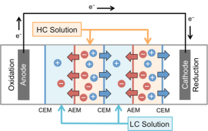
Another application of RED technology is to incorporate small numbers of pairs of membranes in microbial fuel cells (MFCs), called microbial reverse electrodialysis fuel cells (MRFCs) and microbial reverse electrodialysis electrolysis cells (MRECs) (Figure 3). Power generation, compared to that of either of these individual processes (the MFC or RED alone) can be greatly enhanced by combining these two technologies. These systems can be used to generate electricity or hydrogen from renewable energy based on organic wastes and salinity gradients.

Figure 3. (A) Schematic diagram(Source: Kim, Y. and B.E. Logan. 2011. Microbial reverse electrodialysis cells for synergistically enhanced power production. Environ. Sci. Technol. 45(13):5834–5839.)
 Figure 3. (B) Photo of the MRFC system.(Source: Kim, Y. and B.E. Logan. 2011. Microbial reverse electrodialysis cells for synergistically enhanced power production. Environ. Sci. Technol. 45(13):5834–5839.)


